2. BigSimulator (BigNetSim)
Contents
2.1. BigSim Network Simulator
The BigSim Network Simulator is also known as Bigsimulator and lives in the SVN repository https://charm.cs.uiuc.edu/svn/repos/BigNetSim. The Network simulator is actually more of an Inter-connection network simulator and hence more important in the context of large parallel machines with interconnects. The BigSim simulator along with the network simulator is together also known as BigNetSim.
Both the simulators run on top of the POSE framework, which is a Parallel Discrete Event Simulation framework built on top of Charm++.
2.1.1. What does this software do?
BigNetSim is an effort to simulate large current and future computer systems to study the behavior of applications developed for those systems. BigNetSim could be used to study
- new types of interconnection topologies and routing algorithms along with different types of switching architecture.
- application performance on different machines. This uses the API provided in Section 1.5 to run the application on some number of processors on some machine and generate (dump) all events (entry method executions or message send/recv). BigNetSim is used to model the machine that needs to be studied for this application and these logs are then fed into this simulation, and it predicts the performance of this application.
So, the two important uses are studying interconnection networks and performance prediction for applications.
2.1.2. Compiling BigSimulator
To compile the simulator which is called BigSimulator (or BigNetSim), we need the regular Charm++ build (netlrts-linux-x86_64 in our example). It needs to be complemented with a few more libraries from BigSim and with the Pose discrete-event simulator. These pieces can be built, respectively, with:
$ ./build bgampi netlrts-linux-x86_64 -O2
$ ./build pose netlrts-linux-x86_64 -O2
Access to the discrete-event simulation is realized via a Charm++ package originally named BigNetSim (now called BigSimulator). Assuming that the ’subversion’ (svn) package is available, this package can be obtained from the Web with a subversion checkout such as:
$ svn co https://charm.cs.uiuc.edu/svn/repos/BigNetSim/
In the subdir ’trunk/’ created by the checkout, the file Makefile.common must be edited so that ’CHARMBASE’ points to the regular Charm++ installation. Having that done, one chooses a topology in that subdir (e.g. BlueGene for a torus topology) by doing a “cd” into the corresponding directory (e.g. ’cd BlueGene’). Inside that directory, one should simply “make”. This will produce the binary “../tmp/bigsimulator”. That file, together with file “BlueGene/netconfig.vc”, will be used during a simulation. It may be useful to set the variable SEQUENTIAL to 1 in Makefile.common to build a sequential (non-parallel) version of bigsimulator.
2.1.3. Using BigSimulator
BigSimulator (BigNetSim) has 2 major modes.
- Trace based traffic simulation
- Artificial traffic generation based simulation. The mode of the simulator is governed by the \(USE\_TRANSCEIVER\) parameter in the netconfig file. When set to 0, trace based simulation is used, when set to 1, traffic generation is used.
Trace based simulation. This is used to study target application performance, or detailed network performance when loaded by a specific application.
There are two command line parameters for traced based simulation.
./charmrun +p2 ./bigsimulator arg1 arg2
arg1 = 0 => Latency only mode
       1 => Detailed contention model
arg2 = N => starts execution at the time marked by skip point N (0 is start)
2.1.3.1. Simple Latency Model
To use the simple latency model, follow the setup procedure above, noting that the files are located in the trunk/SimpleLatency directory. This will produce the “bigsimulator” file.
The command line parameters used for this model are different. The format is as follows:
[charmrun +p#] bigsimulator -lat <latency> -bw <bandwidth>
             [-cpp <cost per packet> -psize <packet size>]
             [-winsize <window size>] [-skip] [-print_params]
Latency (lat)         - type double; in microseconds
Bandwidth (bw)        - type double; in GB/s
Cost per packet (cpp) - type double; in microseconds
Packet size (psize)   - type int; in bytes
Window size (winsize) - type int; in log entries
The implemented equation is: \(lat + (N/bw) + cpp \times (N/psize)\)
Latency and bandwidth are required. If cost per packet is given, then packet size must be given, as well. Otherwise, cost per packet defaults to 0.0. Packet size, if given, must be a positive integer.
The -winsize flag allows the user to specify the size of the window (number of log entries) used when reading in the bgTrace log files. This is useful if the log files are large. If -winsize is not specified, the value defaults to 0, which indicates that no windowing will be used (i.e., there will be one window for each time line that is equal to the size of the time line).
As with the second parameter in the examples of part (a) of this section, the -skip flag indicates that the simulation should skip forward to the time stamp set during trace creation (see the BigSim tutorial talk from the 2008 Charm++ workshop). If -skip is not included, then no skipping will occur.
The -print_params flag is provided for debugging convenience. When present, the simple latency model parameters will be displayed during simulation initialization.
2.1.3.2. Artificial Traffic Models
Artificial traffic generation based simulation is use to study the performance of interconnects under standard network load schemes.
./bigsimulator arg1 arg2 arg3 arg4 arg5 arg6
example
./bigsimulator 1 2 3 100 2031 0.1
arg1 = 0 => Latency only mode
       1 => Detailed contention model
arg2 = 1 => deterministic traffic
       2 => poisson traffic
arg3 = 1 => KSHIFT
       2 => RING
       3 => BITTRANSPOSE
       4 => BITREVERSAL
       5 => BITCOMPLEMENT
       6 => UNIFORM_DISTRIBUTION
arg4 = number of packets
arg5 = message size
arg6 = load factor
2.1.4. Which Interconnection networks are implemented?
A large number of topologies and routing strategies are implemented in the software. Here, we present a list of interconnection networks. For a complete list of routing strategies, input/output VC selectors, refer to the corresponding directories in the software.
- HyperCube
- FatTree
- DenseGraph
- Three dimensional Mesh
- K-ary-N-cube
- K-ary-N-fly
- K-ary-N-mesh
- K-ary-N-tree
- N-mesh
- Hybrid of Fattree and Dense Graph
- Hybrid of Fattree and HyperCube
2.1.5. Build your own Interconnection network
To build a new interconnection network, one has to create a new directory for that interconnection network and then create the routing strategy, topology, input virtual channel selection and output virtual channel selection strategies for that network. If existing strategies could be used, then reuse them, but if new ones are required, one has to write these new strategies in the corresponding directories for routing, topology, etc.
The InitNetwork function must be provided in InitNetwork.C for this new interconnection network. It builds up all the nodes and switches and NICs and channels that form the network. Look at one of the existing interconnection topologies for reference.
2.1.6. BigNetSim Design and Internals
27 BigNetSim conceptual model
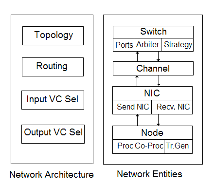
This section focuses on the interconnection network simulation. The entities that form an interconnection network are:
- switch: A switch decides the routing on a packet. Switches could be input buffered or output buffered. The former are implemented as individual posers per port of each switch while the latter are implemented as a poser per switch. In an Input Buffered (IB) switch, a packet in a switch is stored at the input port until its next route is decided and leaves the switch if it finds available space on the next switch in the route. While in an Output Buffered (OB) switch, a packet in a switch decides beforehand on the next route to take and is buffered at the output port until space is available on the next switch along the route. Switches are modeled in much detail. Ports, buffers and virtual channels at ports to avoid head-of-the-line blocking are modeled. Hardware collectives are implemented on the switch to enable broadcasts, multicasts and other collective operations efficiently. These are configurable and can be used if the system being simulated supports them. We also support configurable strategies for arbitration, input virtual channel selection and output virtual channel selection. The configurability of the switch provides a flexible design, satisfying the requirements of a large number of networks.
- network card: Network cards packetize and unpacketize messages. A NIC is implemented as two posers. The sending and receiving entities in a NIC are implemented as separate posers. A NIC is attached to each node.
- channel: These are modeled as posers and connect a NIC to a switch or a switch to another switch.
- compute node: Each compute node connects to a network interface card. A compute node simulates execution of entry methods on it. It is also attached to a message traffic generator, which is used when only an interconnection network is being simulated. This traffic generator can generate any message pattern on each of the compute nodes. The traffic generator can send point-to-point messages, reductions, multicasts, broadcasts and other collective traffic. It supports k-shift, ring, bit-transpose, bit-reversal, bit-complement and uniform random traffic. These are based on common communication patterns found in real applications. The frequency of message generation is determined by a uniform or Poisson distribution.
2.1.7. Topology, Routing and Virtual Channel Selection
Topology, Routing strategies and input and output virtual channel selection strategies need to be decided for any inter-connection network. Once we have all of these in place we can simulate an inter-connection network.
2.1.7.1. Topology
For every architecture one wants to design, a topology file has to written which defines a few basic functions for that particular topology. These are:
void getNeighbours(int nodeid, int numP)
This is called initially for every switch and this populates the data structure next in a switch which contains the connectivity of that switch. The switch specified by switch has numP ports.
int getNext(int portid, int nodeid, int numP)
Returns the index of the switch/node that is connected to the switch nodeid, at portid. The number of ports this node has is numP.
int getNextChannel(int portid, int nodeid, int numP)
Returns the index of the channel that is connected to the switch nodeid, at portid. The number of ports this node has is numP.
int getStartPort(int nodeid, int numP, int dest)
Return the index of the port that is connected to this compute node from a switch
int getStartVc()
Returns the index of the first virtual channel (mostly 0).
int getStartSwitch(int nodeid)
Returns the index of the node/switch that is connected to the first port
int getStartNode()
Returns the index of the first node. Each poser has a separate index, irrespective of the type of the poser.
int getEndNode()
Returns the index of the last node.
2.1.7.2. Routing
Routing strategy needs to be specified for every interconnection network. There is usually at least one routing strategy that needs to be defined for every topology, Usually we have many more. The following functions need to be defined for every routing strategy.
int selectRoute(int current, int dest, int numP, Topology* top, Packet
*p, map<int,int> &bufsize, unsigned short *xsubi)
Returns the portid that should be taken on switch current if the destination is dest. The number of ports on a switch is numP. We also pass the pointer to the topology and to the Packet.
int selectRoute(int current, int dest, int numP, Topology* top, Packet
*p, map<int,int> &bufsize, map<int,int> &portContention, unsigned short
*xsubi)
Returns the portid that should be taken on switch current if the destination is dest. The number of ports on a switch is numP. We also pass the pointer to the topology and to the Packet. Bufsize is the state of the ports in a switch, i.e. how many buffers on each port are full, while portContention is used to give priority to certain ports, when more options are available.
int expectedTime(int src, int dest, POSE_TimeType ovt, POSE_TimeType
origOvt, int length, int *numHops)
Returns the expected time for a packet to travel from src to dest, when the number of hops it will need to travel is numHops.
int convertOutputToInputPort(int id, Packet *p, int numP, int *next)
Translate this output port to input port on the switch this port is connected to.
2.1.7.3. Input Virtual Channel Selection
For every switch, we need to know the mechanism it uses to choose input virtual channel. There are a few different input virtual channel selection strategies, and a switch can choose among them. Each should implement the following function.
int selectInputVc(map<int,int> &availBuffer, map<int,int> &request,
map<int,vector<Header> > &inBuffer, int globalVc, int curSwitch)
Returns the input virtual channel to be used depending on the strategy and the input parameters.
2.1.7.4. Output Virtual Channel Selection
For every switch, we need to know the mechanism it uses to choose output virtual channel. There are a few different output virtual channel selection strategies, and a switch can choose among them. Each should implement the following function.
int selectOutputVc(map<int,int> &bufsize, Packet *p, int unused)
Returns the output virtual channel to be used depending on the strategy and the input parameters.