2. Finite Element Method (FEM) Framework
Contents
2.1. Introduction
The Finite Element Method (FEM) approach is used in many engineering applications with irregular domains, from elastic deformation problems to crack propagation to fluid flow. Charm++ is a free message-passing parallel runtime system for machines from clusters of workstations to tightly-coupled SMPs. The Charm++ FEM framework allows you to write a parallel FEM program, in C or Fortran 90, that closely resembles a serial version but includes a few framework calls.
Using the FEM framework also allows you to take advantage of all the features of Charm++, including run-time load balancing, performance monitoring and visualization, and checkpoint/restart, with no additional effort. The FEM framework also combines naturally with other Charm++ frameworks built on TCHARM.
The FEM framework has been undergoing a wave of recent improvements. A choice to rename the new version ParFUM has been adopted. ParFUM is short for Parallel Framework for Unstructured Meshes. Section 2.10 describes some of the new features included in ParFUM that were not present in FEM.
2.1.1. Philosophy
The Charm++ FEM framework is designed to be flexible, in that it provided a few very general operations, such as loading and partitioning a “mesh.” In describing these operations, we draw on examples from structural analysis, but in fact the same calls can be used for other applications, including fluid dynamics or partial differential equations solvers, or even general-purpose graph manipulation.
For example, the FEM framework does not specify the number of spatial dimensions. Node locations are treated as just another kind of node data, with no restrictions on the number of data items. This allows the FEM framework to work with problems having any number of spatial dimensions.
2.1.2. Terminology
A FEM program manipulates elements and nodes. An element is a portion of the problem domain, also known as a cell, and is typically some simple shape like a triangle, square, or hexagon in 2D; or tetrahedron or rectangular solid in 3D. A node is a point in the domain, and is often the vertex of several elements. Together, the elements and nodes form a mesh, which is the central data structure in the FEM framework.
An element knows which nodes surround it via the element’s connectivity table, which lists the nodes adjacent to each element.
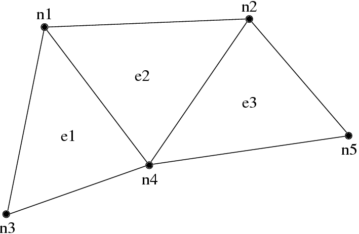
7 3-element, 5 node mesh.
| Element | Adjacent Nodes | ||
|---|---|---|---|
| e1 | n1 | n3 | n4 |
| e2 | n1 | n2 | n4 |
| e3 | n2 | n4 | n5 |
A typical FEM program performs some element-by-element calculations which update adjacent node values; then some node-by-node calculations. For example, a material dynamics program has the structure:
time loop
     element loop-- Element deformation applies forces to
     surrounding nodes
     node loop-- Forces and boundary conditions change node
     positions
end time loop
We can parallelize such FEM programs by partitioning the serial mesh elements into several smaller meshes, or chunks. There is normally at least one chunk per processor; and often even more. During partitioning, we give nodes and elements new, local numbers within that chunk. In the figure below, we have partitioned the mesh above into two chunks, A and B.
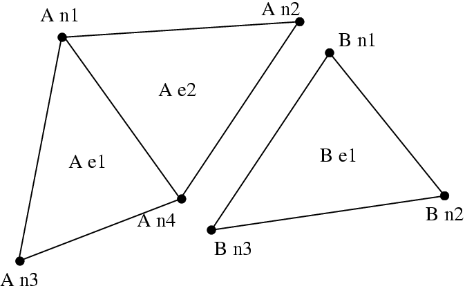
8 Partitioned mesh.
| Element | Adjacent Nodes | ||
|---|---|---|---|
| e1 | n1 | n3 | n4 |
| e2 | n1 | n2 | n4 |
| Element | Adjacent Nodes | ||
|---|---|---|---|
| e1 | n1 | n2 | n3 |
Note that chunk A’s node n2 and B’s node n1 were actually the same node in the original mesh- partitioning split this single node into two shared copies (one on each chunk). However, since adding forces is associative, we can handle shared nodes by computing the forces normally (ignoring the existence of the other chunk), then adding both chunks’ net force for the shared node together. This “node update” will give us the same resulting force on each shared node as we would get without partitioning, thus the same positions, thus the same final result.
For example, under hydrostatic pressure, each chunk might compute a local net force vector for its nodes as shown in Figure 9 (a). After adding forces across chunks, we have the consistent global forces shown in Figure 9 (b).
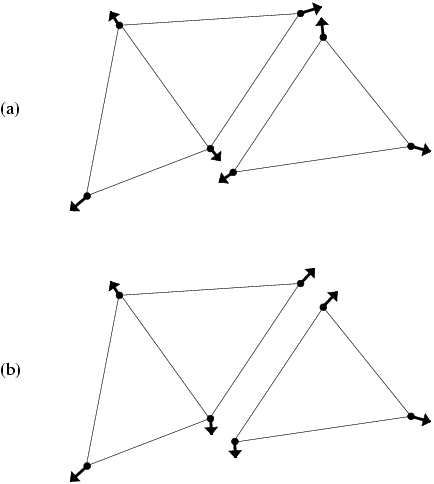
9 A force calculation decomposed across chunks: (a) before update (b) after updating forces across nodes.
Hence, each chunk’s time loop has the structure:
chunk time loop
     element loop-- Element deformation applies forces to
     surrounding nodes
     <update forces on shared nodes>
     node loop-- Forces and boundary conditions change node
     positions
end time loop
This is exactly the form of the time loop for a Charm++ FEM framework program. The framework will accept a serial mesh, partition it, distribute the chunks to each processor, then you run your time loop to perform analysis and communication.
2.1.3. Structure of a Classic FEM Framework Program
A classic FEM framework program consists of two subroutines: init() and driver(). init() is called by the FEM framework only on the first processor - this routine typically does specialized I/O, startup and shutdown tasks. driver() is called for every chunk on every processor, and does the main work of the program. In the language of the TCHARM manual, init() runs in the serial context, and driver() runs in the parallel context.
     subroutine init
          read the serial mesh and configuration data
     end subroutine
/* after init, the FEM framework partitions the mesh */
     subroutine driver
          get local mesh chunk
          time loop
               FEM computations
               communicate boundary conditions
               more FEM computations
          end time loop
     end subroutine
In this mode, the FEM framework sets up a default writing mesh during init(), partitions the mesh after init(), and sets up the partitioned mesh as the default reading mesh during driver().
2.1.4. Structure of an AMPI FEM Framework Program
In addition to the classic init/driver structure above, you can write an FEM framework program using the MPI style. This is a more general, more flexible method of running the program, but it is more complicated than the classic mode. All FEM framework calls are available in either mode.
main program
   MPI_Init
   FEM_Init(MPI_COMM_WORLD)
   if (I am master processor)
      read mesh
   partition mesh
   time loop
       FEM computations
       communicate boundary conditions
       more FEM computations
   end time loop
end main program
In this mode, the FEM framework does not set a default reading or writing mesh, and does no partitioning; so you must use the FEM_Mesh routines to create and partition your mesh. See the AMPI manual for details on how to declare the main routine.
The driver() portion of a classic FEM program strongly resembles an MPI mode main routine—in fact, a classic FEM program can even make MPI calls from its driver() routine, because the FEM framework is implemented directly on top of MPI.
There is even a special shell script for collecting up the FEM framework source code to build a non-Charm, MPI-only version of the FEM framework. To build FEM in this manner, you first build Charm++ normally, then run a script to collect up the neccessary source files (the FEM framework, a small number of Charm configuration and utility files, and the METIS library), and finally build the library using the usual MPI compiler commands:
$ cd charm/
$ ./src/libs/ck-libs/fem/make_fem_alone.sh
$ cd fem_alone/
$ mpicc -I. -DFEM_ALONE=1 -c *.c *.C
$ ar cr libfem_alone.a *.o
You will then have to build your application with the MPI compilers, and manually point to this “fem_alone” directory to find include files and the new FEM library. A typical compiler invocation would be:
$ mpif90 -I$HOME/charm/fem_alone -L$HOME/charm/fem_alone foo.f90 -lfem_alone -o foo
This “standalone”, non-Charm++ method of building the FEM framework prevents the use of load balancing or the other features of Charm++, so we do not recommend it for normal use.
2.1.5. Compilation and Execution
A FEM framework program is a Charm++ program, so you must begin by
downloading the latest source version of Charm++ from
http://charm.cs.uiuc.edu/. Build the source with
./build FEM version or cd into the build directory,
version/tmp, and type make FEM. To compile a FEM program, pass
the -language fem (for C) or -language femf (for Fortran) option
to charmc. You can also build using the “fem_alone” mode described
at the end of the section above.
In a charm installation, see charm/version/pgms/charm++/fem/ for several example and test programs.
At runtime, a Charm++/FEM framework program accepts the following options, in addition to all the usual Charm++ options described in the Charm++ “Installation and Usage Manual”.
+vp\(v\)Create \(v\) mesh chunks, or “virtual processors”. By default, the number of mesh chunks is equal to the number of physical processors (set with
+p\(p\)).-writeSkip driver(). After running init() normally, the framework partitions the mesh, writes the mesh partitions to files, and exits. As usual, the
+vp\(v\) option controls the number of mesh partitions.This option is only used in the classic mode—MPI-style programs are not affected.
-readSkip init(). The framework reads the partitioned input mesh from files and calls driver(). Together with
-write, this option allows you to separate out the mesh preparation and partitioning phase from the actual parallel solution run.This can be useful, for example, if init() requires more memory to hold the unpartitioned mesh than is available on one processor of the parallel machine. To avoid this limitation, you can run the program with
-writeon a machine with a lot of memory to prepare the input files, then copy the files and run with-readon a machine with a lot of processors.-readcan also be useful during debugging or performance tuning, by skipping the (potentially slow) mesh preparation phase. This option is only used in the classic mode—MPI-style programs are not affected.+tcharm_trace femGive a diagnostic printout on every call into the FEM framework. This can be useful for locating a sudden crash, or understanding how the program and framework interact. Because printing the diagnostics can slow a program down, use this option with care.
2.2. FEM Framework API Reference
Some of the routines in the FEM framework have different requirements or meanings depending on where they are called from. When a routine is described as being “called from driver”, this means it is called in the parallel context—from driver() itself, any subroutine called by driver(), or from whatever routine is run by the FEM-attached TCHARM threads. When a routine is described as being “called from init”, this means it is called in the serial context—from init() itself, from any subroutine called from init(), from a routine called by FEM_Update_mesh, or from whatever TCHARM code executes before the FEM_Attach.
2.2.1. Utility
int FEM_Num_partitions();
INTEGER FUNCTION :: FEM_Num_partitions()
Return the number of mesh chunks in the current computation. Can only be called from the driver routine.
int FEM_My_partition();
INTEGER FUNCTION :: FEM_My_partition()
Return the number of the current chunk, from 0 to num_partitions-1. Can only be called from the driver routine.
double FEM_Timer();
DOUBLE PRECISION FUNCTION :: FEM_Timer()
Return the current wall clock time, in seconds. Resolution is machine-dependent, but is at worst 10ms.
void FEM_Print_partition();
SUBROUTINE FEM_Print_partition()
Print a debugging representation of the current chunk’s mesh. Prints the entire connectivity array, and data associated with each local node and element.
void FEM_Print(const char *str);
SUBROUTINE FEM_Print(str)
CHARACTER*, INTENT(IN) ::  str
Print the given string, with “[<chunk number>]” printed before the text.
This routine is no longer required: you can now use the usual printf, PRINT, or WRITE statements.
2.3. Mesh Nodes and Elements
These routines describe and retrieve the finite element mesh for this computation. A mesh, from the framework’s perspective, is a list of elements, nodes, and other data that describes the computational domain. The FEM framework provides extensive support for creating, manipulating, and partitioning meshes.
A serial mesh consists of a single large piece. It’s usually easiest to read and write serial meshes to existing, non-parallel file formats, and it can be easier to manipulate serial meshes. By contrast, a parallel mesh consists of several pieces, called chunks or partitions. Different processors can work on different pieces of a parallel mesh, so most of the computation is done using parallel meshes. A simple program might create or read in a single serial mesh in init, get a local chunk of the partitioned [1] mesh in driver, and work on that chunk for the rest of the program. A more complex program might set an initial mesh in init; then get, work on, reassemble and repartition the mesh several times in driver via FEM_Update_mesh.
2.3.1. Mesh Entity Types
A mesh consists of entities, such as nodes and elements. Entities always have a local number, which is just the entities’ current index in its array. Entites may also have a global number, which is the entity’s index in the unpartitioned serial mesh. Entities have data values called attributes. For example, the location of each node might be called the “location” attribute of the “node” entity type. Attributes are always stored in regular arrays indexed by the entity’s local number. This table lists the different attributes that can be read or written for each type of entity.
A shared entity is a boundary entity that two or more chunks can both update—currently, only nodes can be shared. Shared nodes are mixed in with regular nodes, and the framework currently provides no way to identify which nodes are shared.
A ghost entity is a boundary entity that is asymmetrically shared—one side provides values for the ghost from one of its real entities, and the other sides accept read-only copies of these values. Ghosts are described in more detail in Section 2.5, and can be accessed by adding the constant FEM_GHOST to the corresponding real entity’s type.
The different kinds of entities are described in the following sections.
| Real Entity | Ghost Entity |
|---|---|
| FEM_NODE | FEM_GHOST+FEM_NODE |
| FEM_ELEM+\(elType\) | FEM_GHOST+FEM_ELEM+\(elType\) |
| FEM_SPARSE+\(sparseType\) | FEM_GHOST+FEM_SPARSE+\(sparseType\) |
2.3.1.1. Nodes
FEM_NODE is the entity code for nodes, the simplest kind of entity. A node is a single point in the domain, and elements are defined by their nodes. Nodes can have the following attributes:
- FEM_DATA+\(tag\) Uninterpreted user data, which might include material properties, boundary conditions, flags, etc. User data can have any data type and width. \(tag\) can be any number from 0 to one billion—it allows you to register several data fields with a single entity.
- FEM_GLOBALNO Global node numbers. Always a 1-wide index type.
- FEM_SYMMETRIES Symmetries that apply to this node. Always a 1-wide FEM_BYTE.
- FEM_NODE_PRIMARY Marker indicating that this chunk is responsible for this node. Every node is primary in exactly one chunk. This attribute is always a 1-wide FEM_BYTE containing 0 or 1.
2.3.1.2. Elements
FEM_ELEM+\(elType\) is the entity code for one kind of element. \(elType\) is a small, user-defined value that uniquely identifies this element type. Like nodes, elements can have the attributes FEM_DATA+\(tag\), FEM_GLOBALNO, or FEM_SYMMETRIES; but every element type must have this attribute:
- FEM_CONN Lists the numbers of the nodes around this element. See the description in the ghost section for special ghost connectivity. Always an index type-FEM_INDEX_0 for C-style 0-based node indexing, or FEM_INDEX_1 for Fortran-style 1-based node indexing.
2.3.1.3. Sparse Elements
FEM_SPARSE+\(sparseType\) is the entity code for one kind of sparse element. Again, \(sparseType\) is a small, user-defined unique value. The only difference between ordinary elements and sparse elements regards partitioning. Ignoring ghosts, ordinary elements are never duplicated—each element is sent to its own chunk. Sparse elements may be duplicated, and are always dependent on some other entity for their partitioning. Sparse elements have all the attributes of ordinary elements: FEM_DATA+\(tag\), FEM_GLOBALNO, FEM_SYMMETRIES, and FEM_CONN, as well as the special attribute FEM_SPARSE_ELEM.
Without the FEM_SPARSE_ELEM attribute, a sparse element will be copied to every chunk that contains all the sparse element’s nodes. This is useful for things like node-associated boundary conditions, where the sparse element connectivity might list the nodes with boundary conditions, and the sparse element data might list the boundary condition values.
The FEM_SPARSE_ELEM attribute lists the ordinary element each sparse element should be partitioned with. This attribute consists of pairs (\(elType\),\(elNum\)), indicating that this sparse element should be sent to wherever the \(elNum\)’th FEM_ELEM+\(elType\) is partitioned.
- FEM_SPARSE_ELEM Lists the element we should be partitioned with. The width of this attribute is always 2, and the data type must be an index type-FEM_INDEX_0 or FEM_INDEX_1.
2.3.2. Mesh Entity Manipulation
int FEM_Mesh_default_read(void);
INTEGER function :: FEM_Mesh_default_read()
Return the default reading mesh. This routine is valid:
- From driver(), to return the partitioned mesh.
- During your FEM_Update_mesh routine, to return the assembled mesh.
- Anytime after a call to FEM_Mesh_set_default_read.
int FEM_Mesh_default_write(void);
INTEGER function :: FEM_Mesh_default_write()
Return the default writing mesh. This routine is valid:
- From init(), to change the new serial mesh.
- From driver(), to change the new partitioned mesh.
- During your FEM_Update_mesh routine, to change the new serial mesh.
- Anytime after a call to FEM_Mesh_set_default_write.
int FEM_Mesh_get_length(int mesh,int entity);
INTEGER function :: FEM_Mesh_get_length(mesh,entity)
Return the number of entitys that exist in this mesh.
This call can be used with any entity. For example, to get the number of nodes,
nNodes=FEM_Mesh_get_length(mesh,FEM_NODE)
To get the number of ghost nodes,
nGhostNodes=FEM_Mesh_get_length(mesh,FEM_GHOST+FEM_NODE)
To get the number of real elements of type 2,
nElem=FEM_Mesh_get_length(mesh,FEM_ELEM+2)
void FEM_Mesh_data(int mesh,int entity,int attr, void *data, int
first, int length, int datatype,int width);
SUBROUTINE FEM_Mesh_data(mesh,entity,attr,data,first,length,datatype,width)
INTEGER, INTENT(IN) :: mesh,entity,attr,first,length,datatype,width
datatype, intent(inout) :: data(width,length)
This is the one routine for getting or setting entity’s attributes on the mesh.
mesh A FEM mesh object. Depending on whether this is a reading or writing mesh, this routine reads from or writes to the data array you pass in.
entity A FEM entity code, for example FEM_NODE or FEM_GHOST+FEM_ELEM+1.
attr A FEM attribute code, for example FEM_DATA+\(tag\) or FEM_CONN.
data The user data to get or set. Each row of this array consists of width values, and contains the data values of the attribute for the corresponding entity. This data must be formatted as one of:
datatype :: data(width,length)
datatype :: data(width*length)
first The first entity to affect. In C, this is normally 0; in Fortran, this is normally 1.
length The number of entities to affect. The entities affected are thus those numbered from first to first+length-1. For now, length must be either 1, to touch a single entity; or else the total number of entities-that is, FEM_Mesh_get_length(mesh,entity).
datatype The data type stored in this attribute. This is one of the standard FEM data types FEM_BYTE, FEM_INT, FEM_FLOAT, or FEM_DOUBLE; or else the C-style 0-based index type FEM_INDEX_0 or the Fortran-style 1-based index type FEM_INDEX_1. Alternatively, the equivalent types IDXL_BYTE, IDXL_INT, IDXL_FLOAT, IDXL_DOUBLE, IDXL_INDEX_0, or IDXL_INDEX_1 may be used.
width The number of data items per entity.
For example, to set the element connectivity, which is stored as 3 integer node indices in nodes, you would:
/* C version */
int *nodes=new int[3*nElems];
... fill out nodes ...
FEM_Mesh_data(mesh,FEM_ELEM+1,FEM_CONN, nodes, 0,nElems, FEM_INDEX_0, 3);
... continue to use or delete nodes ...
! F90 version
ALLOCATE(nodes(3,nElems))
... fill out nodes ...
CALL FEM_Mesh_data(mesh,FEM_ELEM+1,FEM_CONN, nodes, 1,nElems, FEM_INDEX_1, 3)
... continue to use or delete nodes ...
To add a new node property with 2 double-precision numbers from an array mat (containing, for example, material properties), you would first pick an unused user data “tag”, for example 13, and:
/* C version */
double *mat=new double[2*nNodes];
...
FEM_Mesh_data(mesh,FEM_NODE, FEM_DATA+13, mat, 0,nNodes, FEM_DOUBLE, 2);
! F90 version
ALLOCATE(mat(2,nNodes))
CALL FEM_Mesh_data(mesh,FEM_NODE,FEM_DATA+13, mat, 1,nNodes, FEM_DOUBLE, 2)
2.3.3. Entity Inquiry
int FEM_Mesh_get_width(int mesh,int entity,int attr);
INTEGER function :: FEM_Mesh_get_width(mesh,entity,attr)
INTEGER, INTENT(IN) :: mesh,entity,attr
Return the width of the attribute attr of entity of mesh. This is the value previously passed as “width” to FEM_Mesh_data.
int FEM_Mesh_get_datatype(int mesh,int entity,int attr);
INTEGER function :: FEM_Mesh_get_datatype(mesh,entity,attr)
INTEGER, INTENT(IN) :: mesh,entity,attr
Return the FEM data type of the attribute attr of entity of mesh. This is the value previously passed as “datatype” to FEM_Mesh_data.
int FEM_Mesh_get_entities(int mesh,int *entities);
INTEGER function :: FEM_Mesh_get_entities(mesh,entities)
INTEGER, INTENT(IN) :: mesh
INTEGER, INTENT(OUT) :: entities(:)
Extract an array of the different entities present in this mesh. Returns the number of entity types present. The entities array must be big enough to hold all the different entities in the mesh.
For example, a simple mesh might have two entity types: FEM_NODE and FEM_ELEM+1.
int FEM_Mesh_get_attributes(int mesh,int entity,int *attributes);
INTEGER function :: FEM_Mesh_get_attributes(mesh,entity,attributes)
INTEGER, INTENT(IN) :: mesh, entity
INTEGER, INTENT(OUT) :: attributes(:)
Extract an array of the different attributes of this entity. Returns the number of attribute types present. The attributes array must be big enough to hold all the attributes.
For example, a simple element might have three attributes: FEM_CONN for node connectivity, FEM_GLOBALNO for global element numbers, and FEM_DATA+7 for a material type.
const char *FEM_Get_entity_name(int entity,char *storage);
const char *FEM_Get_attr_name(int attr,char *storage);
const char *FEM_Get_datatype_name(int datatype,char *storage);
Return a human-readable name for this FEM entity, attribute, or datatype. The storage array must point to a buffer of at least 100 characters; this array might be used as temporary space to store the returned string.
These routines are only available in C.
2.3.4. Advanced Entity Manipulation
void FEM_Mesh_data_offset(int mesh,int entity,int attr, void *data,
int first, int length, int datatype,int width, int offsetBytes,int
distanceBytes,int skewBytes);
SUBROUTINE FEM_Mesh_data_offset(mesh,entity,attr,data,first,length,datatype,width,
offsetBytes,distanceBytes,skewBytes)
INTEGER, INTENT(IN) :: mesh,entity,attr,first,length,datatype,width
INTEGER, INTENT(IN) :: offsetBytes,distanceBytes,skewBytes
datatype, intent(inout) :: data(width,length)
This routine is a more complicated version of FEM_Mesh_data. It allows you to get or set a mesh field directly from a user-defined structure. See the documentation of IDXL_Layout_offset in Section 2.8.2.2 for details on how to set offsetBytes, distanceBytes, and skewBytes.
void FEM_Mesh_data_layout(int mesh,int entity,int attr, void *data,
int firstItem, int length, IDXL_Layout_t layout);
SUBROUTINE FEM_Mesh_data_layout(mesh,entity,attr,data,first,length,layout)
INTEGER, INTENT(IN) :: mesh,entity,attr,first,length,layout
INTEGER, INTENT(IN) :: layout
This routine is a more complicated version of FEM_Mesh_data. Like FEM_Mesh_data_offset, it allows you to get or set a mesh field directly from a user-defined structure; but this routine expects the structure to be described by an IDXL_Layout object.
2.4. Meshes
A “mesh” is a collection of nodes and elements knit together in memory, as described in Section 2.1.2. Meshes are always referred to by an integer that serves as a handle to the local mesh.
This section describes routines to manipulate entire meshes at once: this includes calls to create and delete meshes, read and write meshes, partition and reassemble meshes, and send meshes between processors.
Only a few of the mesh routines are collective; most of them only describe local data and hence operate independently on each chunk.
2.4.1. Mesh Routines
int FEM_Mesh_allocate(void);
INTEGER FUNCTION :: FEM_Mesh_allocate()
Create a new local mesh object. The mesh is initially empty, but it is a setting mesh, so call FEM_Mesh_data to fill the mesh with data.
int FEM_Mesh_deallocate(int mesh);
SUBROUTINE FEM_Mesh_deallocate(mesh)
INTEGER, INTENT(IN) :: mesh
Destroy this local mesh object, and its associated data.
int FEM_Mesh_copy(int mesh);
INTEGER FUNCTION FEM_Mesh_copy(mesh)
INTEGER, INTENT(IN) :: mesh
Create a new mesh object with a separate copy of the data stored in this old mesh object.
void FEM_Mesh_write(int mesh,const char *prefix,int partNo,int
nParts);
SUBROUTINE FEM_Mesh_write(mesh,prefix,partNo,nParts)
INTEGER, INTENT(IN) :: mesh
INTEGER, INTENT(IN) :: partNo,nParts
character (LEN=*), INTENT(IN) :: prefix
Write this mesh to the file “prefix_vppartNo_nParts.dat”.
By convention, partNo begins at 0; but no index conversion is performed so you can assign any meaning to partNo and nParts. In particular, this routine is not collective-you can read any mesh from any processor. For example, if prefix is “foo/bar”, the data for the first of 7 chunks would be stored in “foo/bar_vp0_7.dat” and could be read using FEM_Mesh_read(’foo/bar’,0,7).
Meshes are stored in a machine-portable format internal to FEM. The format is currently ASCII based, but it is subject to change. We strongly recommend using the FEM routines to read and write these files rather than trying to prepare or parse them yourself.
int FEM_Mesh_read(const char *prefix,int partNo,int nParts);
INTEGER FUNCTION :: FEM_Mesh_read(prefix,partNo,nParts)
INTEGER, INTENT(IN) :: partNo,nParts
character (LEN=*), INTENT(IN) :: prefix
Read a new mesh from the file “prefix_vppartNo_nParts.dat”. The new mesh begins in getting mode, so you can read the data out of the mesh using calls to FEM_Mesh_data.
int FEM_Mesh_broadcast(int mesh,int fromRank,FEM_Comm_t comm_context);
INTEGER FUNCTION :: FEM_Mesh_broadcast(mesh,fromRank,comm_context)
INTEGER, INTENT(IN) :: mesh,fromRank,comm_context
Take the mesh mesh on processor fromRank (normally 0), partition the mesh into one piece per processor (in the MPI communicator comm_context, and return each processor its own piece of the partitioned mesh. This call is collective, but only processor fromRank needs to pass in a mesh; the mesh value is ignored on other processors.
For example, if rank 0 has a mesh named “src”, we can partition src for all the processors by executing:
m=FEM_Mesh_broadcast(src,0,MPI_COMM_WORLD);
The new, partitioned mesh is in getting mode, so you can read the partitioned data using calls to FEM_Mesh_data. This call does not affect mesh in any way.
int FEM_Mesh_reduce(int mesh,int toRank,FEM_Comm_t comm_context);
INTEGER FUNCTION :: FEM_Mesh_reduce(mesh,toRank,comm_context)
INTEGER, INTENT(IN) :: mesh,toRank,comm_context
This call is the reverse operation of FEM_Mesh_broadcast: each processor passes in a mesh in mesh, the mesh is assembled, and the function returns the assembled mesh to processor toRank. This call is collective, but only processor toRank is returned a mesh; all other processors are returned the non-mesh value 0.
The new, reassembled mesh is in getting mode. This call does not affect mesh.
2.4.2. Mesh Utility
int FEM_Mesh_is_get(int mesh)
INTEGER FUNCTION ::  FEM_Mesh_is_get(mesh)
INTEGER, INTENT(IN) :: mesh
Return true if this mesh is in getting mode. A getting mesh returns values to FEM_Mesh_data.
int FEM_Mesh_is_set(int mesh)
INTEGER FUNCTION :: FEM_Mesh_is_set(mesh)
INTEGER, INTENT(IN) :: mesh
Return true if this mesh is in setting mode. A setting mesh extracts values from FEM_Mesh_data.
void FEM_Mesh_become_get(int mesh)
SUBROUTINE :: FEM_Mesh_become_get(mesh)
INTEGER, INTENT(IN) :: mesh
Put this mesh in getting mode, so you can read back its values.
void FEM_Mesh_become_set(int mesh)
SUBROUTINE :: FEM_Mesh_become_set(mesh)
INTEGER, INTENT(IN) :: mesh
Put this mesh in setting mode, so you can set its values.
void FEM_Mesh_print(int mesh);
SUBROUTINE FEM_Mesh_print(mesh)
INTEGER, INTENT(IN) :: mesh
Print out a text description of the nodes and elements of this mesh.
2.4.3. Advanced Mesh Manipulation
typedef void (*FEM_Userdata_fn)(pup_er p,void *data);
void FEM_Mesh_pup(int mesh,int pupTag, FEM_Userdata_fn fn, void *data);
SUBROUTINE myPupFn(p,data)
INTEGER, INTENT(IN) :: p
TYPE(myType) :: data

SUBROUTINE FEM_Mesh_pup(mesh,pupTag,myPupFn,data)
INTEGER, INTENT(IN) :: mesh,pupTag
SUBROUTINE :: myPupFn
TYPE(myType) :: data
Store data with this mesh. data is a struct or TYPE with a pup function myPupFn—see the TCharm manual for details on writing a pup function. pupTag is an integer used to distinguish different pieces of data associated with this mesh.
When called on a setting mesh, this routine stores data; when called on a getting mesh, this routine reads out data.
data will be associated with the mesh itself, not any entity in the mesh. This makes it useful for storing shared data, often simulation constants such as the timestep or material properties. data is made a part of the mesh, and it will be read and written, sent and received, partitioned and assembled with the mesh.
void FEM_Mesh_send(int mesh,int toRank,int tag,FEM_Comm_t
comm_context);
SUBROUTINE FEM_Mesh_send(mesh,toRank,tag,comm)
INTEGER, INTENT(IN) :: mesh,toRank,tag,comm
Send the mesh mesh to the processor toRank, using the MPI tag tag and communicator comm_context. Tags are normally only needed if you plan to mix direct MPI calls with your FEM calls.
This call does not affect mesh.
int FEM_Mesh_recv(int fromRank,int tag,FEM_Comm_t comm_context);
INTEGER FUNCTION FEM_Mesh_recv(fromRank,tag,comm)
INTEGER, INTENT(IN) :: fromRank,tag,comm
Receive a new mesh from the processor fromRank, using the MPI tag tag and communicator comm_context. You can also use the special values MPI_ANY_SOURCE as fromRank to receive a mesh from any processor, or use MPI_ANY_TAG for tag to match any tag.
The new mesh is returned in getting mode.
void FEM_Mesh_partition(int mesh,int nParts,int *destMeshes);
SUBROUTINE FEM_Mesh_partition(mesh,nParts,destMeshes)
INTEGER, INTENT(IN) :: mesh,nParts
INTEGER, INTENT(OUT) :: destMeshes(nParts)
Divide mesh into nParts pieces, and store the pieces into the array destMeshes.
The partitioned mesh is returned in getting mode. This is a local call; FEM_Mesh_broadcast is the collective version. This call does not affect the source mesh mesh.
int FEM_Mesh_assemble(int nParts,const int *srcMeshes);
INTEGER FUNCTION FEM_Mesh_assemble(nParts,srcMeshes)
INTEGER, INTENT(IN) :: nParts, srcMeshes(nParts)
Assemble the nParts meshes listed in srcMeshes into a single mesh. Corresponding mesh pieces are matched using the attribute FEM_GLOBALNO. Specifically, if the value of the integer index attribute FEM_GLOBALNO for an entity is \(i\), the entity will be given the number \(i\) in the reassembled mesh. If you do not set FEM_GLOBALNO, the different pieces of the mesh will remain separate—even “matching” nodes will not be merged.
The assembled mesh is returned in getting mode. This is a local call; FEM_Mesh_reduce is the collective version. This call does not affect the source meshes.
void FEM_Mesh_copy_globalno(int src_mesh,int dest_mesh);
SUBROUTINE FEM_Mesh_copy_globalno(src_mesh,dest_mesh)
INTEGER, INTENT(IN) :: src_mesh,dest_mesh
Copy the FEM_GLOBALNO attribute for all the entity types in src_mesh into all the matching types in dest_mesh, where the matching types exist. This call is often used before an FEM_Mesh_assemble or FEM_Mesh_reduce to synchronize global numbers before reassembly.
2.5. Mesh Ghosts
A ghost entity is a local, read-only copy of a real entity on another chunk. Ghosts are typically added to the boundary of a chunk to allow the real (non-ghost) elements at the boundary to access values across the processor boundary. This makes a chunk “feel” as if it was part of a complete unpartitioned mesh; and can be useful with cell-centered methods, and in mesh modification.
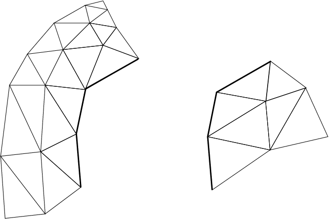
10 A small mesh partitioned into two pieces.

11 The same mesh with one layer of edge-adjacent ghosts.
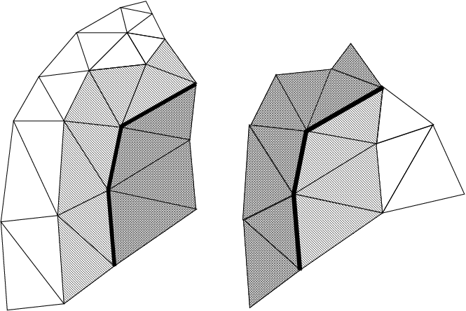
12 The same mesh with one layer of node-adjacent ghosts.
In Figure 10, we begin with a small mesh partitioned into pieces on the left and right. In Figure 11, we have added ghost elements (dark hashing) that share an edge with adjacent real elements (light hatching). In Figure 12, we add ghost elements that share at least one node with adjacent real elements.
2.5.1. Ghost Numbering
Ghosts and real entities are stored by the framework in separate lists—to access the ghost entity type, add FEM_GHOST to the real entity’s type. For example, FEM_GHOST+FEM_ELEM+1 lists the ghost elements for elType 1. To get the number of ghost nodes, you would call FEM_Mesh_get_length(mesh,FEM_GHOST+FEM_NODE).
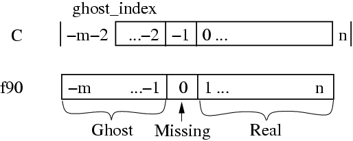
13 Node indices used in the element connectivity array. There are \(n\) real nodes and \(m\) ghosts.
For real elements, the element connectivity always consists of real nodes. But for ghost elements, the adjacent nodes may be missing, or may themselves be ghosts. Thus ghost element connectivity lists may include the invalid value -1 (in C) or 0 (in Fortran) to indicate that the corresponding node is not present; or may include values less than this, which indicate the corresponding node is a ghost. In C, ghost node \(i\) is indicated by the value \(-2-i\), while in Fortran, ghost node \(i\) is indicated by the value \(-i\). This node indexing system is illustrated in Figure 13, This indexing system is bizarre, but it allows us to keep the real and ghost nodes clearly separate, while still allowing real and ghost nodes to be added in increasing order at both ends.
Since the C tests are complicated, in C we recommend using these macros:
- FEM_Is_ghost_index(i) returns true if \(i\) represents a ghost node. In Fortran, use the test \(i\) .lt. \(0\)
- FEM_From_ghost_index(i) returns the ghost node’s index given its connectivity entry. In Fortran, use the expression \(-i\).
- FEM_To_ghost_index(i) returns the connectivity entry for a given ghost node index. In Fortran, again use the expression \(-i\).
For example, a quadrilateral ghost element that is adjacent to, respectively, two real nodes 23 and 17, the tenth local ghost node, and one not-present node might have a connectivity entry of 23,17,-11,-1 (in C) or 23,17,-10,0 (in Fortran).
Applications may wish to use some other numbering, such as by storing all the ghost nodes after all the real nodes. The code to extract and renumber the connectivity of some 3-node triangles stored in FEM_ELEM+2 would be:
/* C version */
int nReal=FEM_Mesh_get_length(mesh,FEM_ELEM+2);
int nGhost=FEM_Mesh_get_length(mesh,FEM_GHOST+FEM_ELEM+2);
typedef int intTriplet[3];
intTriplet *conn=new intTriplet[nReal+nGhost];
/* Extract real triangles into conn[0..nReal-1] */
FEM_Mesh_data(mesh,FEM_ELEM+2,FEM_CONN, &conn[0][0], 0,nReal, 3,FEM_INDEX_0);
/* Extract ghost triangles into conn[nReal..nReal+nGhost-1] */
FEM_Mesh_data(mesh,FEM_GHOST+FEM_ELEM+2,FEM_CONN, &conn[nReal][0], 0,nGhost, 3,FEM_INDEX_0);

/* Renumber the ghost triangle connectivity */
for (int t=nReal;t<nReal+nGhost;t++)
  for (int i=0;i<3;i++) {
    int in=conn[t][i]; /* uses FEM ghost node numbering */
    int out; /* uses application's ghost numbering */
    if (in==-1) {
      out=some_value_for_missing_nodes;
    } else if (FEM_Is_ghost_index(in)) {
      out=first_application_ghost+FEM_From_ghost_index(in);
    } else /*regular real node*/ {
      out=in;
    }
    conn[t][i]=out;
  }
! F90 version
INTEGER, ALLOCATABLE :: conn(3,:)
INTEGER :: nReal,nGhost,t,i,in,out
nReal=FEM_Mesh_get_length(mesh,FEM_ELEM+2)
nGhost=FEM_Mesh_get_length(mesh,FEM_GHOST+FEM_ELEM+2)
ALLOCATE(conn(3,nReal+nGhost))
! Extract real triangles into conn[1..nReal]
CALL FEM_Mesh_data(mesh,FEM_ELEM+2,FEM_CONN, conn, 1,nReal, 3,FEM_INDEX_1)
! Extract ghost triangles into conn[nReal+1..nReal+nGhost]
CALL FEM_Mesh_data(mesh,FEM_GHOST+FEM_ELEM+2,FEM_CONN, conn(1,nReal+1), 1,nGhost, 3,FEM_INDEX_1)

! Renumber the ghost triangle connectivity
DO t=nReal+1,nReal+nGhost
  DO i=1,3
    in=conn(i,t)
    IF (in .EQ. 0) out=some_value_for_missing_nodes
    IF (in .LT. 0) out=first_application_ghost-1+(-in)
    IF (in .GT. 0) out=in
    conn(i,t)=out
  END DO
END DO
2.5.2. Setting up the ghost layer
The framework’s ghost handling is element-centric. You specify which kinds of elements should be ghosts and how they connect by listing their faces before partitioning.
void FEM_Add_ghost_layer(int nodesPerFace,int doAddNodes);
SUBROUTINE FEM_Add_ghost_layer(nodesPerFace,doAddNodes)
INTEGER, INTENT(IN) :: nodesPerFace,doAddNodes
This routine creates a new layer of ghosts around each FEM chunk. nodesPerFace is the number of shared nodes that together form a “face”. doAddNodes specifies that you want ghost nodes around your ghost elements. If doAddNodes is 0, ghost elements will have invalid -1 (in C) or 0 (in Fortran) connectivity entries where there is no corresponding local node.
A face is an unordered “tuple” of nodes, and is an abstract way to describe which ghosts your application needs—an element will be added to your chunk if it connects to at least one of your elements’ faces. For example, if you have a 3D, tetrahedral element that require ghosts on all 4 of its sides, this is equivalent to requiring ghosts of every element that shares all 3 nodes of one of your triangular faces, so for you a face is a 3-node triangle. If you have a 2D shape and want edge-adjacency, for you a face is a 2-node edge. If you want node-adjacent ghosts, a face is a single node.
Calling this routine several times creates several layers of ghost elements, and the different layers need not have the same parameters.
void FEM_Add_ghost_elem(int elType,int facesPerElem,const int
   *elem2face);
SUBROUTINE FEM_Add_ghost_elem(elType,facesPerElem,elem2face)
INTEGER, INTENT(IN) :: elType,facesPerElem
INTEGER, INTENT(IN) :: elem2face(nodesPerFace,facesPerElem)
This call is used to specify which type of element is to be added to the current ghost layer. facesPerElem and elem2face specify a mapping between each element and the surrounding faces. The elem2face table lists, for each face, the nodes of this element which form the face, specified as element-local numbers—indices into this element’s connectivity entry. The elem2face table should have nodesPerFace*facesPerElem entries, and no entry should be greater than nodePerEl for that element type.
Because all faces must take up the same space in the array, elem2face can include special indices— -1 for C, 0 for Fortran—that indicate the corresponding face is actually shorter than usual. For example, if nodesPerFace for this layer is 4, for 4-node quadrilateral faces, you could set one entry in elem2face to -1 to specify this is a 3-node triangular face. Faces of different lengths will never match, so this is just a simple way to add ghosts from two kinds of faces at once.
The above two routines are always used together. For example, if your elements are 3-node triangles and you only require one shared node for inclusion in a single ghost layer, you would use:
FEM_Add_ghost_layer(1,1); /* 1 node per face: node adjacency */
const static int tri2node[]={0,1,2};
FEM_Add_ghost_elem(0,3,tri2node); /* triangles are surrounded by 3 nodes */
If you require two shared nodes (a shared edge), the code will look like:
FEM_Add_ghost_layer(2,1); /* 2 nodes per face: edge adjacency */
const static int tri2edge[]={0,1,  1,2,  2,0};
FEM_Add_ghost_elem(0,3,tri2edge); /*triangles are surrounded by 3 edges */
2.5.3. Symmetries and Ghosts-Geometric Layer
The FEM framework can create ghosts not only of things that are on other processors, but also for various problem symmetries, like mirror reflection, and various types of periodicities. The interface for these ghosts is simple—you ask for the symmetries to be created, then you will get extra ghosts along each symmetry boundary. The symmetry ghosts are updated properly during any communication, even if the symmetry ghosts are ghosts of real local elements from the same chunk.
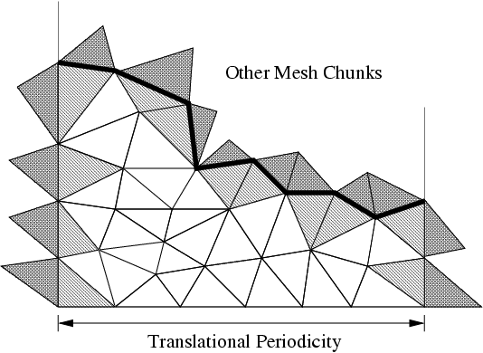
14 Illustrating symmetry ghost elements.
Figure 14 shows a chunk of a mesh for a rectangular domain with horizontal linear translational periodicity—that is, the domain repeats horizontally. Symmetry ghosts lie along the left and right sides; ordinary cross-processor parallel ghosts lie along the top edge where this chunk joins up with the rest of the domain; and the external boundary along the bottom of the chunk has no ghosts.
void FEM_Add_linear_periodicity( int nFaces,int nPer, const int
*facesA,const int *facesB, int nNodes,const double *nodeLocs );
SUBROUTINE FEM_Add_linear_periodicity(nFaces,nPer,facesA,facesB,
nNodes,nodeLocs)
INTEGER, INTENT(IN) :: nFaces, nPer, nNodes
INTEGER, INTENT(IN) :: facesA(nPer,nFaces), facesB(nPer,nFaces)
double precision, INTENT(IN) :: nodeLocs(3,nNodes)
Make facesA and facesB match up under linear translation. Each face of facesA must match up with exactly one face of facesB, but both the faces and the nodes within a face can be permuted in any order—the order is recovered by matching 3d locations in the nodeLocs array.
This call can be repeated, for example if the domain is periodic along several directions. This call can only be issued from init().
void FEM_Sym_coordinates(int elTypeOrMinusOne,double *locs);
SUBROUTINE FEM_Sym_coordinates(elTypeOrZero,locs)
INTEGER, INTENT(IN) :: elTypeOrZero
double precision, intent(inout) :: locs(3,<number of items>)
This call adjusts the 3d locations listed in locs so they respect the symmetries of their corresponding item. If elTypeOrZero is an element type, the locations are adjusted to match with the corresponding element; if elTypeOrZero is zero, the locations are adjusted to match up with the corresponding node.
This call is needed because symmetry ghost nodes and elements initially have their original locations, which must be adjusted to respect the symmetry boundaries. Thus this call is needed both for initial location data (e.g., from FEM_Get_node_data) as well as any communicated location data (e.g., from FEM_Update_ghost_field).
This call can only be issued from driver().
2.5.4. Advanced Symmetries and Ghosts-Lower Layer
The geometric symmetry layer in the preceding section is actually a thin wrapper around this lower, more difficult to use layer.
void FEM_Set_sym_nodes(const int *canon,const int *sym);
SUBROUTINE FEM_Set_sym_nodes(canon,sym)
INTEGER, INTENT(IN) :: canon(nNodes)
INTEGER, INTENT(IN) :: sym(nNodes)
This call describes all possible symmetries in an extremely terse format. It can only be called from init(). The “canonicalization array” canon maps nodes to their canonical representative—if canon(\(i\))=canon(\(j\)), nodes \(i\) and \(j\) are images of each other under some symmetry. The sym array has bits set for each symmetry boundary passing through a node.
For example, a 2d domain with 6 elements A, B, C, D, E, and F and 12 nodes numbered 1-12 that is mirror-symmetric on the horizontal boundaries but periodic in the vertical boundaries would look like:
 D^'|  D^ |  E^ |  F^ |  F^`
 -  1  -  2  -  3  -  4  -
 A' |  A  |  B  |  C  |  C`
 -  5  -  6  -  7  -  8  -
 D' |  D  |  E  |  F  |  F`
 -  9  - 10  -  11 -  12 -
 Av'|  Av |  Bv |  Cv |  Cv`

v indicates the value has been shifted down (bottom boundary),
^ indicates the value has been shifted up (top boundary),
' indicates the value has been copied from the left (right boundary),
` indicates the value has been copied from the right (left boundary).
If we mark the left border with 1, the top with 2, the right with 4, and the bottom with 8, this situation is indicated by topologically pasting the top row to the bottom row by setting their canon entries equal, and marking each node with its symmetries.
| Node | canon | sym |
|---|---|---|
| 1 | 1 | 3 (left + top) |
| 2 | 2 | 2 (top) |
| 3 | 3 | 2 (top) |
| 4 | 4 | 6 (top + right) |
| 5 | 5 | 1 (left) |
| 6 | 6 | 0 (none) |
| 7 | 7 | 0 (none) |
| 8 | 8 | 4 (right) |
| 9 | 1 | 9 (left+bottom) |
| 10 | 2 | 8 (bottom) |
| 11 | 3 | 8 (bottom) |
| 12 | 4 | 12 (bottom+right) |
void FEM_Get_sym(int elTypeOrMinusOne,int *destSym);
SUBROUTINE FEM_Get_sym(elTypeOrZero,destSym);
INTEGER, INTENT(IN) :: elTypeOrMinusOne
INTEGER, INTENT(OUT) :: destSym(nItems)
This call extracts the list of symmetry conditions that apply to an item type. If elType is an element type, it returns the symmetry conditions that apply to that element type; if elType is -1 (zero for Fortran), it returns the symmetry conditions that apply to the nodes. Symmetry conditions are normally only nonzero for ghost nodes and elements.
Mirror symmetry conditions are not yet supported, nor are multiple layers of symmetry ghosts, but both should be easy to add without changing this interface.
2.6. Older Mesh Routines
These routines have a simpler, but less flexible interface than the general routines described in Section 2.3. Because they are easy to implement in terms of the new routines, they will remain part of the framework indefinitely. These routines always use the default mesh, as returned by FEM_Mesh_default_read and FEM_Mesh_default_write.
void FEM_Set_elem(int elType,int nEl,int doublePerEl,int nodePerEl);
void FEM_Get_elem(int elType,int *nEl,int *doublePerEl,int
*nodePerEl);
SUBROUTINE FEM_Set_elem(elType,nEl,doublePerEl,nodePerEl)
INTEGER, INTENT(IN) :: elType,nEl,doublePerEl,nodePerEl
SUBROUTINE FEM_Get_elem(elType,nEl,doublePerEl,nodePerEl)
INTEGER, INTENT(IN) :: elType
INTEGER, INTENT(OUT) :: nEl,doublePerEl,nodePerEl
Describe/retrieve the number and type of elements. ElType is a user-defined small, unique element type tag. nEl is the number of elements being registered. doublesPerEl and nodePerEl are the number of doubles of user data, and nodes (respectively) associated with each element.
doublePerEl or nodePerEl may be zero, indicating that no user data or connectivity data (respectively) is associated with the element.
You can make this and any other mesh setup calls in any order—there is no need to make them in linearly increasing order. However, for a given type of element FEM_Set_elem must be called before setting that element’s connectivity or data.
void FEM_Set_elem_conn(int elType,const int *conn);
void FEM_Get_elem_conn(int elType,int *conn);
SUBROUTINE FEM_Set_elem_conn_r(elType,conn)
INTEGER, INTENT(IN) :: elType
INTEGER, INTENT(IN), dimension(nodePerEl,nEl) :: conn
SUBROUTINE FEM_Get_elem_conn_r(elType,conn)
INTEGER, INTENT(IN) :: elType
INTEGER, INTENT(OUT), dimension(nodePerEl,nEl) :: conn
SUBROUTINE FEM_Set_elem_conn_c(elType,conn)
INTEGER, INTENT(IN) :: elType
INTEGER, INTENT(IN), dimension(nEl,nodePerEl) :: conn
SUBROUTINE FEM_Get_elem_conn_c(elType,conn)
INTEGER, INTENT(IN) :: elType
INTEGER, INTENT(OUT), dimension(nEl,nodePerEl) :: conn
Describe/retrieve the element connectivity array for this element type. The connectivity array is indexed by the element number, and gives the indices of the nodes surrounding the element. It is hence nodePerEl*nEl integers long.
The C version array indices are zero-based, and must be stored in row-major order (a given element’s surrounding nodes are stored contiguously in the conn array). The Fortran version indices are one-based, and are available in row-major (named _r) and column-major (named _c) versions. We recommend row-major storage because it results in better cache utilization (because the nodes around an element are stored contiguously).
In this older interface, ghost nodes are indicated by invalid,
void FEM_Set_node(int nNode,int doublePerNode);
void FEM_Get_node(int
  *nNode,int *doublePerNode);
SUBROUTINE FEM_Set_node(nNode,doublePerNode)
INTEGER, INTENT(IN) :: nNode,doublePerNode
SUBROUTINE FEM_Get_node(nNode,doublePerNode)
INTEGER, INTENT(OUT) :: nNode,doublePerNode
Describe/retrieve the number of nodes and doubles of user data associated with each node. There is only one type of node, so no nodeType identifier is needed.
doublePerNode may be zero, indicating that no user data is associated with each node.
2.6.1. Old Mesh Data
void FEM_Set_node_data(const double *data);
void FEM_Get_node_data(double *data);
void FEM_Set_elem_data(int elType,const double *data);
void FEM_Get_elem_data(int elType,double *data);
SUBROUTINE FEM_Set_node_data_r(data)
REAL*8, INTENT(IN), dimension(doublePerNode,nNode) :: data
SUBROUTINE FEM_Get_node_data_r(data)
REAL*8, INTENT(OUT), dimension(doublePerNode,nNode) :: data
SUBROUTINE FEM_Set_node_data_c(data)
REAL*8, INTENT(IN), dimension(nNode,doublePerNode) :: data
SUBROUTINE FEM_Get_node_data_c(data)
REAL*8, INTENT(OUT), dimension(nNode,doublePerNode) :: data
SUBROUTINE FEM_Set_elem_data_r(elType,data)
INTEGER, INTENT(IN) :: elType
REAL*8, INTENT(IN), dimension(doublePerElem,nElem) :: data
SUBROUTINE FEM_Get_elem_data_r(elType,data)
INTEGER, INTENT(IN) :: elType
REAL*8, INTENT(OUT), dimension(doublePerElem,nElem) :: data
SUBROUTINE FEM_Set_elem_data_c(elType,data)
INTEGER, INTENT(IN) :: elType
REAL*8, INTENT(IN), dimension(nElem,doublePerElem) :: data
SUBROUTINE FEM_Get_elem_data_c(elType,data)
INTEGER, INTENT(IN) :: elType
REAL*8, INTENT(OUT), dimension(nElem,doublePerElem) :: data
Describe/retrieve the optional, uninterpreted user data associated with each node and element. This user data is partitioned and reassembled along with the connectivity matrix, and may include initial conditions, node locations, material types, or any other data needed or produced by the program. The Fortran arrays can be row- or column- major (see FEM_Set_elem_conn for details). The row-major form is preferred.
2.6.2. Old Ghost Numbering
In this older version of the framework, FEM_Get_node and FEM_Get_elem return the total number of nodes and elements, including ghosts. The routines below return the index of the first ghost node or element, where ghosts are numbered after all the real elements. This old ghost numbering scheme does not work well when adding new ghosts, which is why the new ghost numbering scheme describes in Section 2.5.1 is used in the new API.
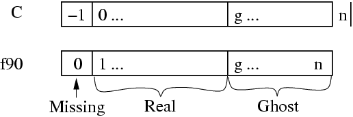
15 Old ghost element and node numbering. FEM_Get_ghost_returns \(g\), FEM_Get_returns \(n\).
int FEM_Get_node_ghost(void);
int FEM_Get_elem_ghost(int elemType);
The examples below iterate over the real and ghost elements using the old numbering:
// C version:
int firstGhost,max;
FEM_Get_node(&max, &ignored);
firstGhost=FEM_Get_node_ghost();
for (i=0;i<firstGhost;i++)
       //... i is a real node...
for (i=firstGhost;i<max;i++)
       //... i is a ghost node ...
! Fortran version:
call FEM_Get_node(max,ignored);
firstGhost=FEM_Get_node_ghost();
do i=1,firstGhost-1
!       ... i is a real node...
end do
do i=firstGhost,max
!      ... i is a ghost node...
end do
2.6.3. Old Backward Compatibility
void FEM_Set_mesh(int nElem, int nNodes, int nodePerEl,const int*
conn);
This is a convenience routine equivalent to:
FEM_Set_node(nNodes,0);
FEM_Set_elem(0,nElem,0,nodePerEl);
FEM_Set_elem_Conn(0,conn);
SUBROUTINE FEM_Set_mesh(nElem,nNodes,nodePerEl,conn)
This is a convenience routine equivalent to:
CALL FEM_Set_node(nNodes,0)
CALL FEM_Set_elem(1,nElem,0,nodePerEl)
CALL FEM_Set_elem_Conn_c(1,conn)
2.6.4. Old Sparse Data
Sparse data is typically used to represent boundary conditions. For example, in a structural dynamics program typically some nodes have an imposed force or position. The routines in this section are used to describe this kind of mesh-associated data—data that only applies to some “sparse” subset of the nodes or elements.
void FEM_Set_sparse(int S_id,int nRec, const int *nodes,int
nodesPerRec, const void *data,int dataPerRec,int dataType);
SUBROUTINE FEM_Set_sparse(S_id,nRec,nodes,nodesPerRec,data,dataPerRec,dataType)
INTEGER, INTENT(IN) :: S_id,nRec,nodesPerRec,dataPerRec,dataType
INTEGER, INTENT(IN) :: nodes(nodesPerRec,nRec)
varies, INTENT(IN) :: data(dataPerRec,nRec)
Register nRec sparse data records with the framework under the number S_id. The first call to FEM_Set_sparse must give a S_id of zero in C (1 in fortran); and subsequent calls to FEM_Set_sparse must give increasing consecutive S_ids.
One sparse data record consists of some number of nodes, listed in the nodes array, and some amount of user data, listed in the data array. Sparse data records are copied into the chunks that contains all that record’s listed nodes. Sparse data records are normally used to describe mesh boundary conditions- for node-associated boundary conditions, nodesPerRec is 1; for triangle-associated boundary conditions, nodesPerRec is 3.
In general, nodePerRec gives the number of nodes associated with each sparse data record, and nodes gives the actual node numbers. dataPerRec gives the number of data items associated with each sparse data record, and dataType, one of FEM_BYTE, FEM_INT, FEM_REAL, or FEM_DOUBLE, gives the type of each data item. As usual, you may change or delete the nodes and data arrays after this call returns.
For example, if the first set of sparse data is 17 sparse data records, each containing 2 nodes stored in bNodes and 3 integers stored in bDesc, we would make the call:
/*C version*/
FEM_Set_sparse(0,17, bNodes,2, bDesc,3,FEM_INT);
! Fortran version
CALL FEM_Set_sparse(1,17, bNodes,2, bDesc,3,FEM_INT)
void FEM_Set_sparse_elem(int S_id,const int *rec2elem);
SUBROUTINE FEM_Set_sparse_elem(S_id,rec2elem)
INTEGER, INTENT(IN) :: S_id
INTEGER, INTENT(IN) :: rec2elem(2,nRec)
Attach the previously-set sparse records S_id to the given elements. rec2elem consists of pairs of integers—one for each sparse data record. The first integer in the pair is the element type to attach the sparse record to, and the second integer gives the element number within that type. For example, to attach the 3 sparse records at S_id to the elements numbered 10, 11, and 12 of the element type elType, use:
/*C version*/
int rec2elem[]={elType,10, elType,11, elType,12};
FEM_Set_sparse_elem(S_id,rec2elem);
! Fortran version
integer :: rec2elem(2,3);
rec2elem(1,:)=elType
rec2elem(2,1)=10; rec2elem(2,2)=11; rec2elem(2,3)=12;
CALL FEM_Set_sparse_elem(S_id,rec2elem)
int FEM_Get_sparse_length(int S_id);
void FEM_Get_sparse(int S_id,int *nodes,void *data);
function FEM_Get_sparse_length(S_id);
INTEGER, INTENT(IN) :: S_id
INTEGER, INTENT(OUT) :: FEM_Get_sparse_Length
SUBROUTINE FEM_Get_sparse(S_id,nodes,data);
INTEGER, INTENT(IN) :: S_id
INTEGER, INTENT(OUT) :: nodes(nodesPerRec,FEM_Get_sparse_Length(S_id))
varies, INTENT(OUT) :: data(dataPerRec,FEM_Get_sparse_Length(S_id))
Retrieve the previously registered sparse data from the framework. FEM_Get_sparse_length returns the number of records of sparse data registered under the given S_id; zero indicates no records are available. FEM_Get_sparse returns you the actual nodes (translated to local node numbers) and unchanged user data for these sparse records.
In this old interface, there is no way to access sparse ghosts.
2.7. Mesh Modification
void FEM_Update_mesh(FEM_Update_mesh_fn routine, int
callMeshUpdated,int doWhat);
SUBROUTINE FEM_Update_mesh(routine,callMeshUpdated,doWhat)
external, INTENT(IN) :: routine
INTEGER, INTENT(IN) :: callMeshUpdated,doWhat
Reassemble the mesh chunks from each partition into a single serial mesh, and call the given routine on the assembled mesh. In this routine, which runs on processor 0, the FEM_Get and FEM_Set routines can manipulate the serial mesh. The parameter callMeshUpdated, which must be non-zero, is passed down to routine as routine(callMeshUpdated).
FEM_Get calls from driver() will only return the new mesh after a FEM_Update_mesh call where doWhat is FEM_MESH_UPDATE; otherwise FEM_Get from driver() will still return the old mesh. FEM_Update_mesh can only be called from driver; and must be called by the driver routine for every chunk.
| doWhat | Numeric | Repartition? | FEM_Update_mesh |
|---|---|---|---|
| FEM_MESH_OUTPUT | 0 | No | driver() continues alongside routine |
| FEM_MESH_FINALIZE | 2 | No | driver() blocks until routine finishes |
| FEM_MESH_UPDATE | 1 | Yes | driver() blocks for the new partition |
For example, FEM_Update_mesh(my_output_routine, k, FEM_MESH_OUTPUT) reassembles the mesh and calls a routine named my_output_routine(k) while the driver routines continue with the computation. This might be useful, for example, for writing out intermediate solutions as a single file; writing outputs from driver() is more efficient but often results in a separate file for each mesh chunk.
To block the driver routines during a call to a routine named my_finalize_routine(k), such as at the end of the computation when the drivers have no other work to do, use FEM_Update_mesh(my_finalize_routine, k, FEM_MESH_FINALIZE).
To reassemble, modify, and repartition the mesh, use FEM_Update_mesh(my_update_routine, k, FEM_MESH_UPDATE). It may be easier to perform major mesh modifications from my_update_routine(k) than the drivers, since the entire serial mesh is available to my_update_routine(k).
FEM_Update_mesh reassembles the serial mesh with an attempt to preserve the element and node global numbering. If the new mesh has the same number and type of elements and nodes, the global numbers (and hence serial mesh) will be unchanged. If new elements or nodes are added at each chunk, they will be assigned new unique global numbers. If elements or nodes are removed, their global numbers are not re-used- you can detect the resulting holes in the serial mesh since the user data associated with the deleted elements will be all zero. Generally, however, it is less error-prone to perform mesh modifications only in driver() or only in an update routine, rather than some in both.
2.8. IDXL Communication
The FEM framework’s communication layer is called IDXL. This small library handles sending and receiving data to and from a sparse subset of 1D indices into a user array. The sparse index subset is called an “Index List”, hence the name of the library.
2.8.1. Index Lists
An Index List is the fundamental data structure of the IDXL library—for example, the list of shared nodes is an Index List. IDXL includes routines for building, combining, and sending and receiving Index Lists.
An Index List, as you might expect, is a list of indices that need to be sent and received. An Index List includes both the indices that need to be sent, as well as the indices to be received, from each chunk.
Consider two chunks \(a\) and \(b\) where \(b\) needs some information \(a\) has, such as if \(b\) has ghosts of real elements on \(a\). \(a\)’s Index List thus has a send portion with the \(a\)-local indices for the elements \(a\) sends; and \(b\)’s Index List contains a receive portion with the \(b\)-local indices for the elements \(b\) receives. Thus across processors, the corresponding send and receive portions of \(a\) and \(b\)’s Index Lists match, as shown in Figure 16.
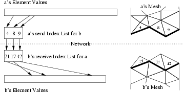
16 Illustrating how Index Lists match up \(a\)’s source elements with \(b\)’s ghost elements.
2.8.1.1. Index List Calls
You refer to an Index List via an opaque handle—in C, the integer typedef IDXL_t; in Fortran, a bare INTEGER.
IDXL_t FEM_Comm_shared(int mesh,int entity);
INTEGER function FEM_Comm_shared(mesh,entity)
INTEGER, INTENT(IN) :: mesh,entity
Return a read-only copy of the Index List of shared nodes. The send and receive portions of this list are identical, because each shared node is both sent and received. Shared nodes are most often used with the send/sum communication pattern.
Must be called from driver. mesh must be a reading mesh. entity must be FEM_NODE. You may not call IDXL_Destroy on the returned list.
IDXL_t FEM_Comm_ghost(int mesh,int entity);
INTEGER function FEM_Comm_ghost(mesh,entity)
INTEGER, INTENT(IN) :: mesh,entity
Return a read-only copy of the Index List of ghost entities. The send portion of this list contains real, interior entities, which are sent away; the receive portion of the list contains the ghost entites, which are received. Ghosts are most often used with the send/recv communication pattern.
Elements to be sent out are listed starting at zero (one in Fortran); but ghost elements to be received are also listed starting at zero (one in Fortran). If real and ghost elements are kept in separate arrays, this is usable as-is; but if ghosts and real elements are kept together, you will need to shift the ghost indices using IDXL_Combine or IDXL_Shift.
This routine must be called from driver. mesh must be a reading mesh. entity must not include FEM_GHOST-ghosts are already included. You may not call IDXL_Destroy on the returned list.
IDXL_t IDXL_Create(void);
INTEGER function IDXL_Create()
Create a new, empty Index List. This list can then be filled up using IDXL_Copy or IDXL_Combine.
Must be called from driver. You must eventually call IDXL_Destroy on the returned list.
void IDXL_Combine(IDXL_t dest,IDXL_t src,int startSend,int startRecv);
SUBROUTINE IDXL_Combine(dest,src,startSend,startRecv)
INTEGER, INTENT(IN) :: dest,src,startSend,startRecv
Add the shifted contents of the src Index List to dest. The send portion of src is shifted so the first index sent will be startSend; for a ghost index list this is the index of the first sent real entity. The receive portion of src is similarly shifted so the first index received will be startRecv; for a ghost index list this is the index of the first received ghost entity.
This routine does not check for duplicates—if an index originally appears in dest and the also in the shifted src, it will be listed twice.
2.8.1.2. Advanced Index List Calls
void IDXL_Destroy(IDXL_t l);
SUBROUTINE IDXL_Destroy(l)
INTEGER, INTENT(IN) :: l
Destroy this Index List, and free the list storage allocated by the framework. Only call this routine with lists you created using IDXL_Create; not lists obtained directly from the FEM framework.
void IDXL_Print(IDXL_t l);
SUBROUTINE IDXL_Print(l)
INTEGER, INTENT(IN) :: l
Print out the contents of this Index List. This routine shows both the send and receive indices on the list, for each chunk we communicate with.
void IDXL_Copy(IDXL_t dest,IDXL_t src);
SUBROUTINE IDXL_Print(dest,src)
INTEGER, INTENT(IN) :: dest,src
Copy the contents of the source Index List into the destination Index List, which should be empty.
void IDXL_Shift(IDXL_t l,int startSend,int startRecv);
SUBROUTINE IDXL_Shift(l,startSend,startRecv)
INTEGER, INTENT(IN) :: l,startSend,startRecv
Like IDXL_Combine, but only shifts the indices within a single list.
void IDXL_Add_entity(int newIdx,int nBetween,int *between);
SUBROUTINE IDXL_Add_node(newIdx,nBetween,between)
INTEGER, INTENT(IN) :: newIdx,nBetween
INTEGER, INTENT(IN) :: between(nBetween)
This call adds a new entity, with local index newIdx, to this Index List. The new entity is sent or received by each chunk that sends or receives all the entities listed in the between array. For example, when adding a new node along an edge, nBetween is 2 and between lists the endpoints of the edge; this way if the edge is shared with some chunk, the new node will be shared with that chunk.
This routine only affects the current chunk- no other chunks are affected. To ensure the communication lists match, IDXL_Add_entity must be called on all the chunks that send or receive the entity, to create the local copies of the entity.
IDXL_Add_entity adds the new entity to the end of the communication list, and so must be called in the same order on all the chunks that share the new entity. For example, if two new nodes \(x\) and \(y\) are added between chunks \(a\) and \(b\), if chunk \(a\) calls IDXL_Add_entity with its local number for \(x\) before it calls IDXL_Add_entity with its local number for \(y\), chunk \(b\) must also add its copy of node \(x\) before adding \(y\).
2.8.2. Data Layout
IDXL is designed to send and receive data directly out of your arrays, with no intermediate copying. This means IDXL needs a completely general method for specifying how you store your data in your arrays. Since you probably don’t change your storage layout at runtime, you can create a “data layout” once at the beginning of your program, then use it repeatedly for communication.
IDXL Layouts are normally used to describe arrays of data associated with nodes or elements. The layout abstraction allows you to use IDXL routines to communicate any sort of data, stored in a variety of formats.
Like Index Lists, Layouts are referred to via an opaque handle—in a C program via the integer typedef IDXL_Layout_t, and in Fortran via a bare integer.
2.8.2.1. Layout Routines
In most programs, the data to be communicated is a dense array of data of one type. In this case, there is only one layout routine you need to know:
IDXL_Layout_t IDXL_Layout_create(int type,int width);
INTEGER function IDXL_Layout_create(type,width)
INTEGER, INTENT(IN) :: type,width
The simplest data layout to describe—a dense array of this IDXL datatype, indexed by entity number, with width pieces of data per entity. Note that the number of entities is not stored with the layout-the number of entities to be communicated depends on the communication routine.
The IDXL datatypes are:
| IDXL Datatype | C Datatypes | Fortran Datatypes |
|---|---|---|
| IDXL_BYTE | unsigned char | INTEGER*1 |
| char | LOGICAL*1 | |
| IDXL_INT | int | INTEGER |
| IDXL_REAL | float | SINGLE PRECISION |
| REAL*4 | ||
| IDXL_DOUBLE | double | DOUBLE PRECISION |
| REAL*8 |
For example, if you keep a dense array with 3 doubles of force per node, you’d call this routine as:
// C++ version:
double *force=new double[3*n];
IDXL_Layout_t force_layout=IDXL_Layout_create(IDXL_DOUBLE,3);
! F90 Version
double precision, allocatable :: force(:,:)
integer :: force_layout
ALLOCATE(force(3,n)) ! (could equivalently use force(3*n) )
force_layout=IDXL_Layout_create(IDXL_DOUBLE,3)
This routine was once called FEM_Create_simple_field.
2.8.2.2. Advanced Layout Routines
These advanced routines are only needed if you want to exchange data stored in an array of user-defined types. Most programs only need IDXL_Layout_create.
IDXL_Layout_t IDXL_Layout_offset(int type, int width, int offsetBytes,
int distanceBytes,int skewBytes);
INTEGER function IDXL_Layout_offset(type,width,offsetBytes,distanceBytes,skewBytes)
INTEGER, INTENT(IN) :: type,width,offsetBytes,distanceBytes,skewBytes
The most general data layout-an array indexed by entity, containing width pieces of data per entity. This routine expands on IDXL_Layout_create by adding support for user-defined types or other unusual data layouts. You describe your layout by giving various in-memory byte offsets that describe the data is stored. Again, the number of entities is not stored with the layout-the number of entities to be communicated depends on the communication routine.
- offsetBytes The number of bytes from the start of the array to the start of the data.
- distanceBytes The number of bytes taken by one entity.
- skewBytes The number of bytes between each piece of data. Since this can almost always be determined from the size of the base data type, this parameter can be left as zero.
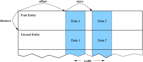
17 Describing a complex data layout.
For example, if your node data is all stored in a struct (in fortran, a named TYPE), offsetBytes gives the distance between the start of the struct and the force; and distanceBytes gives the size in bytes of the struct.
In C, the offsetof and sizeof keywords are useful for finding these values. In Fortran, we provide a special routine called foffsetof that returns the distance, in bytes, between its two arguments.
// C++ version:
typedef struct {
   double d[3], v[3], force[3], a[3];
   double m;
} node;
node *nodes=new node[n];
IDXL_Layout_t force_layout=IDXL_Layout_offset(IDXL_DOUBLE,3,
         offsetof(node,force),sizeof(node),0);
! F90 Version
  TYPE node
     DOUBLE PRECISION :: d(3), v(3), force(3), a(3)
     DOUBLE PRECISION :: m
  END TYPE
  integer :: force_layout
  ALLOCATE(nodes(n))
  force_layout=IDXL_Layout_create(IDXL_DOUBLE,3,
&          foffsetof(nodes(1),nodes(1)%force),
&          foffsetof(nodes(1),nodes(2)),0)
void IDXL_Layout_destroy(IDXL_Layout_t layout);
SUBROUTINE IDXL_Layout_destroy(layout)
INTEGER, INTENT(IN) :: layout
Destroy this Layout. You only need call this routine if you repeatedly create layouts.
int IDXL_Get_layout_type(IDXL_Layout_t layout);
INTEGER function IDXL_Get_layout_type(layout)
Return the IDXL datatype for this layout.
int IDXL_Get_layout_width(IDXL_Layout_t layout);
INTEGER function IDXL_Get_layout_width(layout)
Return the layout width—the number of data items that are communicated per entity.
int IDXL_Get_layout_distance(IDXL_Layout_t layout);
INTEGER function IDXL_Get_layout_distance(layout)
Return the layout distance—the number of bytes between successive entity’s data items.
2.8.2.3. Layout Compatibility Routines
Before IDXL was made a separate library, FEM included these routines, which are still preserved for backward compatibility.
IDXL_Layout_t FEM_Create_simple_field(int type,int width);
INTEGER function FEM_Create_simple_field(type,width)
INTEGER, INTENT(IN) :: type,width
This routine is completely interchangeable to IDXL_Layout_create.
int FEM_Create_field(int type,int width,int offset,int distance);
INTEGER function FEM_Create_field(type, width, offset, distance)
INTEGER, INTENT(IN) :: type, width, offset, distance
This routine is like a call to IDXL_Layout_offset with the rarely used skewBytes set to zero.
2.8.3. IDXL Communication
This section brings together all the pieces of IDXL: Index Lists are used to determine what to send and what to receive and Layouts are used to determine where to get and put the communicated data.
2.8.3.1. Communication Routines
void IDXL_Comm_sendsum(IDXL_Comm_t comm,IDXL_t indices,IDXL_Layout_t
layout,void *data);
SUBROUTINE IDXL_Comm_sendsum(comm,indices,layout,data)
INTEGER, INTENT(IN) :: comm,indices,layout
varies, INTENT(INOUT) :: data
Sum these indices of shared entities across all chunks that share them. The user data array is interpreted according to the given layout.
If comm is zero, this routine is blocking and finishes the communication immediately. If comm is not zero, this routine is non-blocking and equivalent to a call to IDXL_Comm_send followed by a call to IDXL_Comm_sum.
This routine is typically used to sum up partial values on shared nodes. It is a more general version of the old FEM routine FEM_Update_field. For example, to sum up the shared-node values in a 3d force vector indexed by node, you would use:
// C++ version:
double *force=new double[3*nNodes];
IDXL_Layout_t force_layout=IDXL_Layout_create(IDXL_DOUBLE,3);
IDXL_t shared_indices=FEM_Comm_shared(mesh,FEM_NODE);

//... in the time loop ...
    IDXL_Comm_sendsum(0,shared_indices,force_layout,force);
! F90 Version
double precision, allocatable :: force(:,:)
integer :: force_layout, shared_indices
ALLOCATE(force(3,nNodes)) ! (could equivalently use force(3*nNodes) )
force_layout=IDXL_Layout_create(IDXL_DOUBLE,3)
shared_indices=FEM_Comm_shared(mesh,FEM_NODE)

!... in the time loop ...
    CALL IDXL_Comm_sendsum(0,shared_indices,force_layout,force)
void IDXL_Comm_sendrecv(IDXL_Comm_t comm,IDXL_t indices,IDXL_Layout_t
layout,void *data);
SUBROUTINE IDXL_Comm_sendrecv(comm,indices,layout,data)
INTEGER, INTENT(IN) :: comm,indices,layout
varies, INTENT(INOUT) :: data
Send these (typically real) send indices and copy in these (typically ghost) receive indices. The user data array is interpreted according to the given layout.
If comm is zero, this routine is blocking and finishes the communication immediately. If comm is not zero, this routine is non-blocking and equivalent to a call to IDXL_Comm_send followed by a call to IDXL_Comm_sum.
This routine is typically used to obtain the values of ghost entities. It is a more general version of the old FEM routine FEM_Update_ghost_field. For example, to obtain 7 solution values per ghost element, storing gElem ghosts in the array just after the nElem regular elements, we could:
// C++ version:
double *elem=new double[7*(nElem+gElem)];
IDXL_Layout_t elem_layout=IDXL_Layout_create(IDXL_DOUBLE,7);
IDXL_t ghost_original=FEM_Comm_ghost(mesh,FEM_ELEM+1);
IDXL_t ghost_shifted=IDXL_Create(); // ghosts start at nElem
IDXL_Combine(ghost_shifted,ghost_original,0,nElem);

//... in the time loop ...
    IDXL_Comm_sendrecv(0,ghost_shifted,elem_layout,elem);
! F90 Version
double precision, allocatable :: elem(:,:)
integer :: elem_layout, ghost_original,ghost_shifted
ALLOCATE(elem(7,nElem+gElem))
elem_layout=IDXL_Layout_create(IDXL_DOUBLE,7)
ghost_original=FEM_Comm_ghost(mesh,FEM_ELEM+1)
ghost_shifted=IDXL_Create() ! ghosts start at nElem+1
CALL IDXL_Combine(ghost_shifted,ghost_original,1,nElem+1)

!... in the time loop ...
    CALL IDXL_Comm_sendrecv(0,ghost_shifted,elem_layout,elem)
2.8.3.2. Advanced Communication Routines
IDXL_Comm_t IDXL_Comm_begin(int tag,int context);
INTEGER function IDXL_Comm_begin(tag,context)
INTEGER, INTENT(IN) :: tag,context
Start a non-blocking communication operation with this (user-defined) tag and communication context (0, or an AMPI communicator).
Every call to this routine must eventually be matched by a call to IDXL_Comm_wait. Warning: for now, tag and context are ignored, and there can be only one outstanding communication operation.
void IDXL_Comm_send(IDXL_Comm_t comm,IDXL_t indices,IDXL_Layout_t
layout,const void *data);
SUBROUTINE IDXL_Comm_send(comm,indices,layout,data)
INTEGER, INTENT(IN) :: comm,indices,layout
varies, INTENT(IN) :: data
When comm is flushed, send these send indices, with this layout, from this data array.
This routine is always non-blocking; as the data array passed in will not be copied out until the call to IDXL_Comm_flush.
void IDXL_Comm_recv(IDXL_Comm_t comm,IDXL_t indices,IDXL_Layout_t
layout,void *data);
SUBROUTINE IDXL_Comm_recv(comm,indices,layout,data)
INTEGER, INTENT(IN) :: comm,indices,layout
varies, INTENT(OUT) :: data
When comm is finished, copy in these receive indices, with this layout, into this data array.
This routine is always non-blocking; as the data array passed in will not be copied into until the call to IDXL_Comm_wait.
void IDXL_Comm_sum(IDXL_Comm_t comm,IDXL_t indices,IDXL_Layout_t
layout,void *data);
SUBROUTINE IDXL_Comm_sum(comm,indices,layout,data)
INTEGER, INTENT(IN) :: comm,indices,layout
varies, INTENT(INOUT) :: data
When comm is finished, add in the values for these receive indices, with this layout, into this data array.
This routine is always non-blocking; as the data array passed in will not be added to until the call to IDXL_Comm_wait.
void IDXL_Comm_flush(IDXL_Comm_t comm);
SUBROUTINE IDXL_Comm_flush(comm)
INTEGER, INTENT(IN) :: comm
Send all outgoing data listed on this comm. This routine exists because there may be many calls to IDXL_Comm_send, and sending one large message is more efficient than sending many small messages.
This routine is typically non-blocking, and may only be issued at most once per IDXL_Comm_begin.
void IDXL_Comm_wait(IDXL_Comm_t comm);
SUBROUTINE IDXL_Comm_wait(comm)
INTEGER, INTENT(IN) :: comm
Finish this communication operation. This call must be issued exactly once per IDXL_Comm_begin. This call includes IDXL_Comm_flush if it has not yet been called.
This routine always blocks until all incoming data is received, and is the last call that can be made on this comm.
2.9. Old Communication Routines
(This section is for backward compatibility only. The IDXL routines are the new, more flexible way to perform communication.)
The FEM framework handles the updating of the values of shared nodes- that is, it combines shared nodes’ values across all processors. The basic mechanism to do this update is the “field”- numeric data items associated with each node. We make no assumptions about the meaning of the node data, allow various data types, and allow a mix of communicated and non-communicated data associated with each node. The framework uses IDXL layouts to find the data items associated with each node in memory.
Each field represents a (set of) data records stored in a contiguous array, often indexed by node number. You create a field once, with the IDXL layout routines or FEM_Create_field, then pass the resulting field ID to FEM_Update_field (which does the shared node communication), FEM_Reduce_field (which applies a reduction over node values), or one of the other routines described below.
void FEM_Update_field(int Fid,void *nodes);
SUBROUTINE FEM_Update_field(Fid,nodes)
INTEGER, INTENT(IN) :: Fid
varies, INTENT(INOUT) :: nodes
Combine a field of all shared nodes with the other chunks. Sums the value of the given field across all chunks that share each node. For the example above, once each chunk has computed the net force on each local node, this routine will sum the net force across all shared nodes.
FEM_Update_field can only be called from driver, and to be useful, must be called from every chunk’s driver routine.
After this routine returns, the given field of each shared node will be the same across all processors that share the node.
This routine is equivalent to an IDXL_Comm_Sendsum operation.
void FEM_Read_field(int Fid,void *nodes,char *fName);
SUBROUTINE FEM_Read_field(Fid,nodes,fName)
INTEGER, INTENT(IN) :: Fid
varies, INTENT(OUT) :: nodes
CHARACTER*, INTENT(IN) :: fName
Read a field out of the given serial input file. The serial input file is line-oriented ASCII- each line begins with the global node number (which must match the line order in the file), followed by the data to be read into the node field. The remainder of each line is unread. If called from Fortran, the first line must be numbered 1; if called from C, the first line must be numbered zero. All fields are separated by white space (any number of tabs or spaces).
For example, if we have called Create_field to describe 3 doubles, the input file could begin with
1    0.2    0.7    -0.3      First node
2    0.4    1.12   -17.26    another node
...
FEM_Read_field must be called from driver at any time, independent of other chunks.
This routine has no IDXL equivalent.
void FEM_Reduce_field(int Fid,const void *nodes,void *out,int op);
SUBROUTINE FEM_Reduce_field(Fid,nodes,outVal,op)
INTEGER, INTENT(IN) :: Fid,op
varies, INTENT(IN) :: nodes
varies, INTENT(OUT) :: outVal
Combine one record per node of this field, according to op, across all chunks. Shared nodes are not double-counted- only one copy will contribute to the reduction. After Reduce_field returns, all chunks will have identical values in outVal, which must be vec_len copies of base_type.
May only be called from driver, and to complete, must be called from every chunk’s driver routine.
op must be one of:
- FEM_SUM- each element of outVal will be the sum of the corresponding fields of all nodes
- FEM_MIN- each element of outVal will be the smallest value among the corresponding field of all nodes
- FEM_MAX- each element of outVal will be the largest value among the corresponding field of all nodes
This routine has no IDXL equivalent.
void FEM_Reduce(int Fid,const void *inVal,void *outVal,int op);
SUBROUTINE FEM_Reduce(Fid,inVal,outVal,op)
INTEGER, INTENT(IN) :: Fid,op
varies, INTENT(IN) :: inVal
varies, INTENT(OUT) :: outVal
Combine one record of this field from each chunk, according to op, across all chunks. Fid is only used for the base_type and vec_len- offset and dist are not used. After this call returns, all chunks will have identical values in outVal. Op has the same values and meaning as FEM_Reduce_field.
May only be called from driver, and to complete, must be called from every chunk’s driver routine.
! C example
double inArr[3], outArr[3];
int fid=IDXL_Layout_create(FEM_DOUBLE,3);
FEM_Reduce(fid,inArr,outArr,FEM_SUM);
! f90 example
DOUBLE PRECISION :: inArr(3), outArr(3)
INTEGER fid
fid=IDXL_Layout_create(FEM_DOUBLE,3)
CALL FEM_Reduce(fid,inArr,outArr,FEM_SUM)
This routine has no IDXL equivalent.
2.9.1. Ghost Communication
It is possible to get values for a chunk’s ghost nodes and elements from the neighbors. To do this, use:
void FEM_Update_ghost_field(int Fid, int elTypeOrMinusOne, void
*data);
SUBROUTINE FEM_Update_ghost_field(Fid,elTypeOrZero,data)
INTEGER, INTENT(IN) :: Fid,elTypeOrZero
varies, INTENT(INOUT) :: data
This has the same requirements and call sequence as FEM_Update_field, except it applies to ghosts. You specify which type of element to exchange using the elType parameter. Specify -1 (C version) or 0 (fortran version) to exchange node values.
2.9.2. Ghost List Exchange
It is possible to exchange sparse lists of ghost elements between FEM chunks.
void FEM_Exchange_ghost_lists(int elemType,int nIdx,const int
*localIdx);
SUBROUTINE FEM_Exchange_ghost_lists(elemType,nIdx,localIdx)
INTEGER, INTENT(IN) :: elemType,nIdx
INTEGER, INTENT(IN) :: localIdx[nIdx]
This routine sends the local element indices in localIdx to those neighboring chunks that connect to its ghost elements on the other side. That is, if the element localIdx[i] has a ghost on some chunk c, localIdx[i] will be sent to and show up in the ghost list of chunk c.
int FEM_Get_ghost_list_length(void);
Returns the number of entries in my ghost list—the number of my ghosts that other chunks passed to their call to FEM_Exchange_ghost_lists.
void FEM_Get_ghost_list(int *retLocalIdx);
SUBROUTINE FEM_Get_ghost_list(retLocalIdx)
INTEGER, INTENT(OUT) :: retLocalIdx[FEM_Get_ghost_list_length()]
- These routines access the list of local elements sent by other chunks.
- The returned indices will all refer to ghost elements in my chunk.
2.10. ParFUM
ParFUM is the name for the latest version of FEM. ParFUM includes additional features including parallel mesh modification and adaptivity (geometrical). ParFUM also contains functions which generate additional topological adjacency information. ParFUM cannot be built separate from Charm++ since it uses various messaging mechanisms that MPI does not readily support. It is important to note that ParFUM adaptivity at the moment has some limitations. It works only for meshes which are two-dimensional. The other limitation is that the mesh on which it works on must have one layer of node-deep ghosts. Most applications require no or one layer ghosts, so it is really not a limitation, but for applications that need multiple layers of ghost information, the adaptivity operations cannot be used.
2.10.1. Adaptivity Initialization
If a FEM application wants to use parallel mesh adaptivity, the first task is to call the initialization routine from the driver function. This creates the node and element adjacency information that is essential for the adaptivity operations. It also initializes all the mesh adaptivity related internal objects in the framework.
void FEM_ADAPT_Init(int meshID)
Initializes the mesh defined by meshID for the mesh adaptivity operations.
2.10.2. Preparing the Mesh for Adaptivity
For every element entity in the mesh, there is a desired size entry for each element. This entry is called meshSizing. This meshSizing entry contains a metric that decides the element quality. The default metric is the average of the size of the three edges of an element. This section provides various mechanisms to set this field. Some of the adaptive operations actually use these metrics to maintain quality. Though there is another metric which is computer for each element and maintained on the fly and that is the ratio of the largest length to the smallest altitude and this value during mesh adaptivity is not allowed to go beyond a certain limit. Because the larger this value after a certain limit, the worse the element quality.
void FEM_ADAPT_SetElementSizeField(int meshID, int elem, double size);
For the mesh specified by meshID, for the element elem, we set the desired size for each element to be size.
void FEM_ADAPT_SetElementSizeField(int meshID, double *sizes);
For the mesh specified by meshID, for the element elem, we set the desired size for each element from the corresponding entry in the sizes array.
void FEM_ADAPT_SetReferenceMesh(int meshID);
For each element int this mesh defined by meshID set its size to the average edge length of the corresponding element.
void FEM_ADAPT_GradateMesh(int meshID, double smoothness);
Resize mesh elements to avoid jumps in element size. i.e. avoid discontinuities in the desired sizes for elements of a mesh by smoothing them out. Algorithm based on h-shock correction, described in Mesh Gradation Control, Borouchaki et al.
2.10.3. Modifying the Mesh
Once the elements in the mesh has been prepared by specifying their desired sizes, we are ready to use the actual adaptivity operations. Currently we provide Delaunay flip operations, edge bisect operations and edge-coarsen operations all of which are implemented in parallel, but the user has access to these wrapper functions which intelligently decide when and in which region of the mesh to use the adaptivity operations to generate a mesh with higher quality elements while achieving the desired size (which is usually average edge length per element), or it could even be the area of each element.
void FEM_ADAPT_Refine(int meshID, int qm, int method, double
factor,double *sizes);
Perform refinements on the mesh specified by meshId. Tries to maintain/improve element quality by refining the mesh as specified by a quality measure qm. If method = 0, refine areas with size larger than factor down to factor If method = 1, refine elements down to sizes specified in the sizes array. In this array each entry corresponds to the corresponding element. Negative entries in sizes array indicate no refinement.
void FEM_ADAPT_Coarsen(int meshID, int qm, int method, double
factor,double *sizes);
Perform refinements on the mesh specified by meshId. Tries to maintain/improve element quality by coarsening the mesh as specified by a quality measure qm. If method = 0, coarsen areas with size smaller than factor down to factor If method = 1, coarsen elements up to sizes specified in the sizes array. In this array each entry corresponds to the corresponding element. Negative entries in sizes array indicate no coarsening.
void FEM_ADAPT_AdaptMesh(int meshID, int qm, int method, double
factor,double *sizes);
It has the same set of arguments as required by the previous two operations, namely refine and coarsen. This function keeps using the above two functions till we have all elements in the mesh with as close to the desired quality. Apart from using the above two operations, it also performs a mesh repair operation where it gets rid of some bad quality elements by Delaunay flip or coarsening as the geometry in the area demands.
int FEM_ADAPT_SimpleRefineMesh(int meshID, double targetA, double xmin,
double ymin, double xmax, double ymax);
A region is defined by (xmax, xmin, ymax, ymin) and the target area to be achieved for all elements in this region in the mesh specified by meshID is given by targetA. This function only performs a series of refinements on the elements in this region. If the area is larger, then no coarsening is done.
int FEM_ADAPT_SimpleCoarsenMesh(int meshID, double targetA, double xmin,
double ymin, double xmax, double ymax);
A region is defined by (xmax, xmin, ymax, ymin) and the target area to be achieved for all elements in this region in the mesh specified by meshID is given by targetA. This function only performs a series of coarsenings on the elements in this region. If the area is smaller, then no refinement is done.
2.10.4. Verify correctness of the Mesh
After adaptivity operations are performed and even before adaptivity operations, it is important to first verify that we are working on a mesh that is consistent geometrically with the types of mesh that the adaptivity algorithms are designed to work on. There is a function that can be used to test various properties of a mesh, like area, quality, geometric consistency, idxl list correctness, etc.
void FEM_ADAPT_TestMesh(int meshID);
This provides a series of tests to determine the consistency of the mesh specified by meshID.
These four simple steps define what needs to be used by a program that wishes to use the adaptivity features of ParFUM.
2.10.5. ParFUM developers
This manual is meant for ParFUM users, so developers should look at the source code and the doxygen generated documentation.
| [1] | The framework uses the excellent graph partitioning package Metis. |